



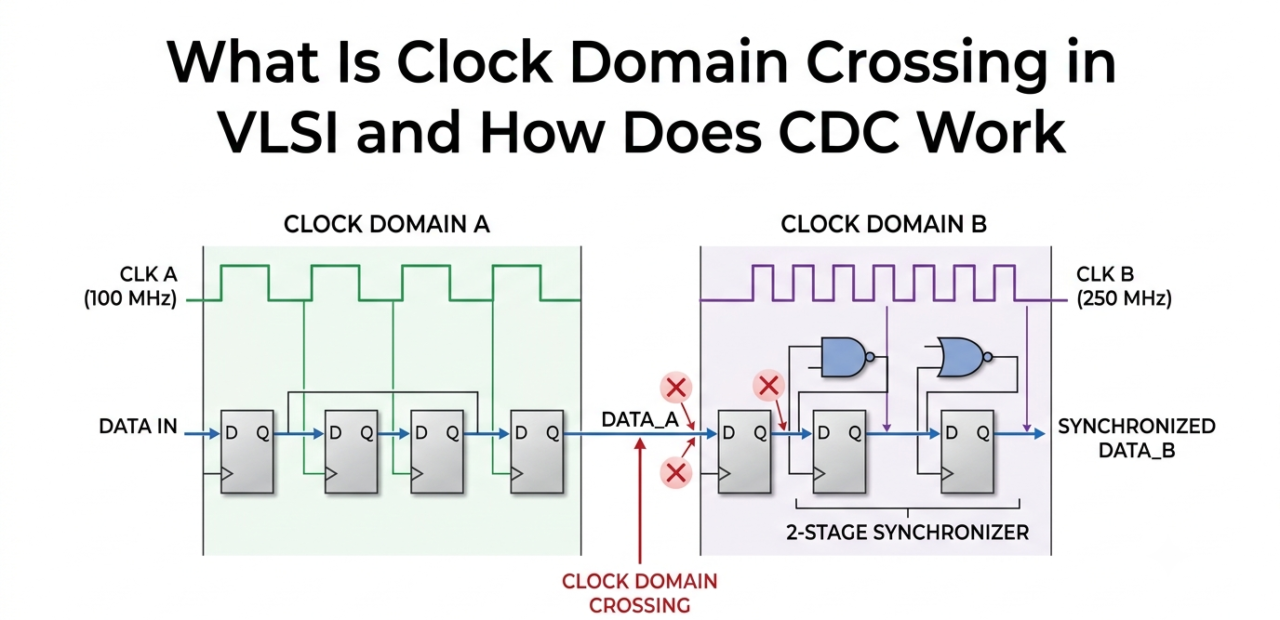
What Is Clock Domain Crossing in VLSI and How Does CDC Work?

Modern System-on-Chip (SoC) architectures incorporate millions of transistors operating across multiple asynchronous clock domains to balance processing speed, throughput, and power efficiency. Clock Domain Crossing (CDC) in VLSI occurs whenever a signal originates in one clock domain and is sampled by a flip-flop powered by an independent, asynchronous clock domain. Because these clocks lack a constant phase relationship or predictable frequency alignment, data transfers across domains cannot guarantee traditional setup and hold timing compliance. Consequently, understanding CDC fundamentals is essential for chip design and verification engineers aiming to prevent catastrophic post-silicon functional failures.
In complex integrated circuits, unsynchronized signals traveling between distinct clock regions frequently induce metastability, functional data loss, and severe timing violations. Aspiring physical design and RTL verification engineers must master specialized CDC techniques—such as multi-flop synchronizers, handshake protocols, and asynchronous FIFOs—to guarantee data integrity across boundaries. Enrolling in specialized career programs at a reputed VLSI training institute in India provides hands-on exposure to industry-standard static sign-off tools like SpyGlass CDC and Questa CDC, equipping engineers with practical problem-solving expertise required for advanced semiconductor roles.
Summary Comparison of CDC Synchronization Approaches
| Synchronization Strategy | Ideal Signal / Data Type | Latency Overhead | Throughput Capacity | Hardware Complexity |
| Two Flip-Flop (2-FF)wo Flip-Flop (2-FF) | Single-bit control signals | 2 Destination Clock Cycles | Low (Control signals) | Minimal (2 Registers) |
| Handshake Protocol | Unsynchronized multi-bit data | High (Multi-cycle round trip) | Low to Medium | Moderate (Control FSMs) |
| Asynchronous FIFO | Continuous multi-bit data streams | Medium (Read/Write pointer delay) | High (Full Bus Width) | High (Dual-Port RAM + Gray Pointers) |
| Gray Code Pointer | Monotonic multi-bit counters | 2 Destination Clock Cycles | High for Sequential Data | Moderate (Binary/Gray Converters) |
1. Fundamentals of Clock Domain Crossing (CDC)
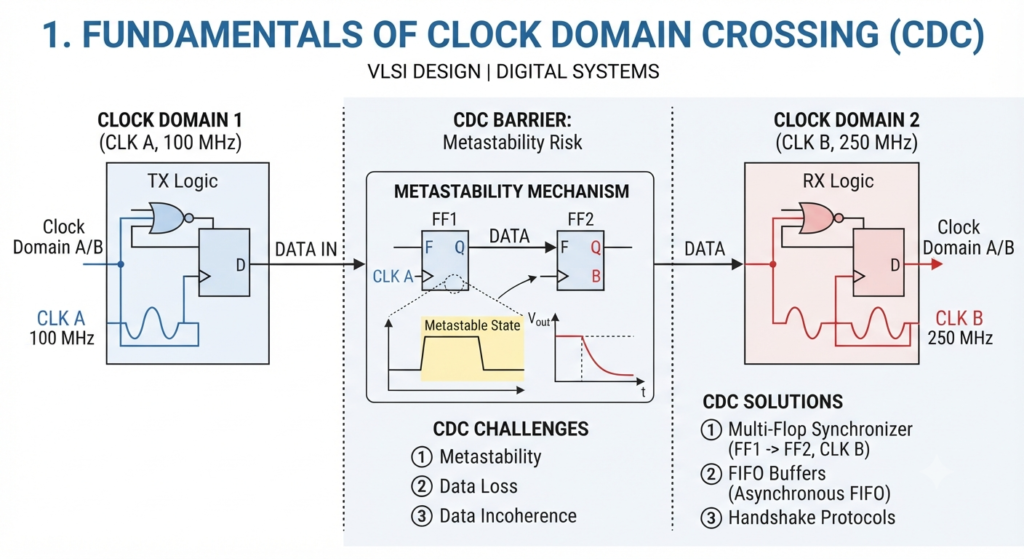
In digital Integrated Circuit (IC) design, a clock domain is defined as a group of sequential storage elements driven by a single clock source or multiple clocks with a fixed, predictable phase relationship. When signals must cross boundaries between completely independent clocks, the interface is classified as a Clock Domain Crossing. Unlike synchronous transfers where setup and hold checks ensure safe data capture, asynchronous crossings lack deterministic phase alignment. Without proper CDC handling, the receiving flip-flop risks sampling data while it transitions, leading to non-deterministic circuit behaviors and system-level functional failure.
Modern SoCs utilize dozens of independent clock domains to optimize dynamic power dissipation and computational throughput across heterogeneous modules like DSPs, memory controllers, and serial buses. Managing CDC boundaries requires engineers to analyze how control signals and multi-bit data buses transition between asynchronous regions. Understanding these structural boundaries allows design teams to implement reliable synchronization strategies, avoiding logic inconsistencies that traditional Static Timing Analysis (STA) tools cannot detect on asynchronous paths.
2. Understanding Metastability and Functional Risks
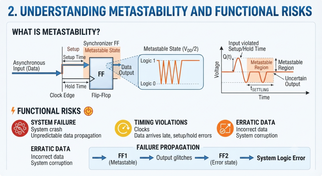
Metastability occurs when a flip-flop’s data input violates the setup or hold time requirement relative to the active clock edge. Under these invalid timing conditions, the internal bistable element enters an indeterminate voltage state between high and low logic levels. The output remains stuck in this unstable state for an unpredictable period before settling to either a logic ‘0’ or ‘1’. If this unstable output propagates into downstream combinational logic, different gates may interpret the voltage level differently, causing system crashes and severe functional glitches.
Beyond raw metastability, unmanaged CDC boundaries introduce structural anomalies like data loss and signal coherency failure. When a fast clock domain transmits data to a slower domain without proper handshaking, high-frequency pulses may vanish uncaptured. Conversely, passing multiple asynchronous data bits without multi-bit synchronization causes individual bits to arrive at different clock cycles due to bus skew. These combined failure modes make metastability and unsynchronized CDC paths among the most critical root causes of silent hardware failures in high-speed digital systems.
3. Core CDC Synchronization Techniques
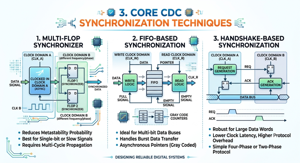
To mitigate metastability risks, digital engineers deploy specialized hardware synchronizer circuits tailored to the transferred signal type. For single-bit control signals, the standard approach is a Two-Flip-Flop (2-FF) synchronizer. The first flip-flop absorbs the high probability of metastability, granting the signal an entire clock period to settle before the second flip-flop samples it cleanly into the destination domain. While 2-FF structures add latency, they dramatically increase the Mean Time Between Failures (MTBF) for asynchronous single-bit control paths.
When transferring multi-bit data vectors, basic 2-FF synchronizers cannot be applied directly to every bit because differential interconnect delays cause bit-skew. Instead, design teams implement robust multi-bit synchronization architectures like Gray code encoding, Request/Acknowledge hardware handshakes, or asynchronous FIFOs. Gray coding ensures that only one bit changes per state transition, eliminating vector coherency errors during pointer transfers. For high-bandwidth continuous data transfers, dual-port asynchronous FIFOs read and write data reliably across independent domains.
4. Static and Dynamic CDC Verification Methodologies
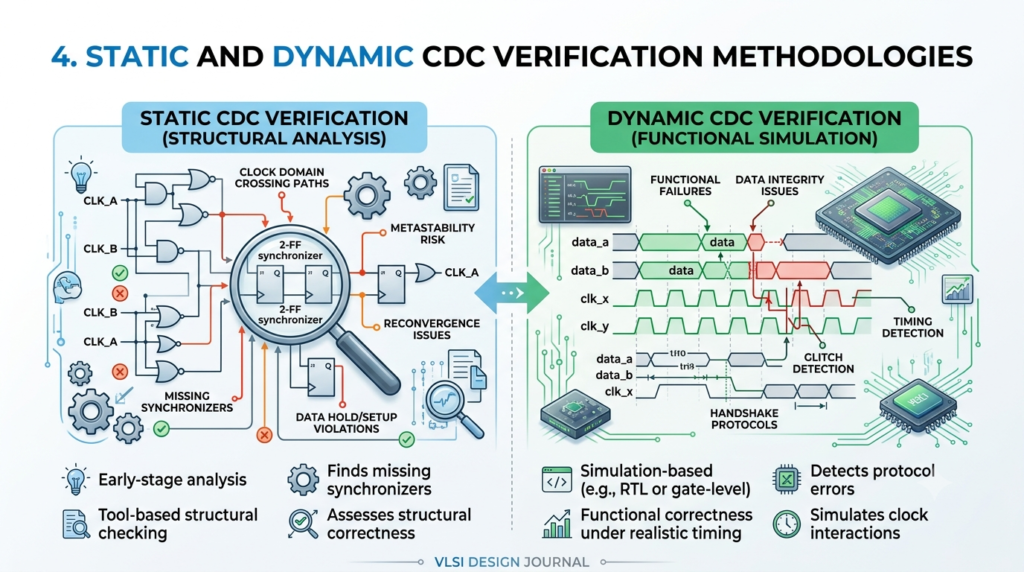
Traditional Static Timing Analysis (STA) algorithms assume fixed phase relationships between clocks, making them ineffective at identifying asynchronous CDC errors. To ensure robust verification, design teams rely on dedicated Static CDC Checkers such as Synopsys SpyGlass or Siemens Questa CDC. These specialized tools parse structural RTL code to detect unsynchronized crossings, improper synchronizers, combinational logic placed on CDC paths, and incorrect Gray code conversions long before physical synthesis begins.
Complementing static checks, dynamic CDC verification utilizes specialized simulation models that inject artificial metastable delays and random jitter into asynchronous signal crossings. This approach uncovers functional bugs caused by variable synchronization latency and control-data alignment failures that structural analysis might miss. Integrating automated static CDC sign-off with target dynamic assertion suites ensures comprehensive coverage, preventing costly post-silicon rebuilds.
5. Industry Best Practices for CDC Structural Design
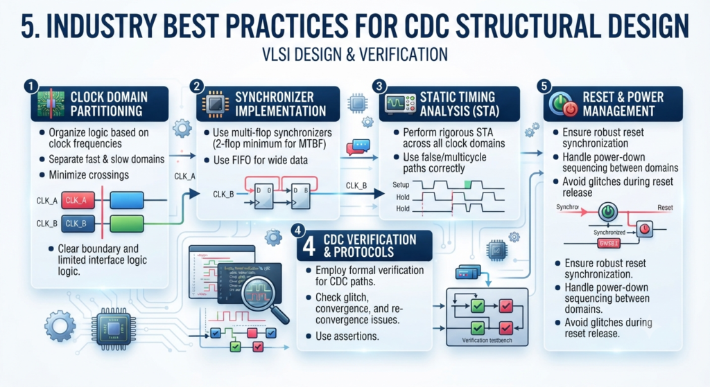
Adhering to strict RTL design guidelines minimizes CDC vulnerabilities from the start of a digital architecture project. A primary rule is to avoid placing combinational logic on CDC boundaries. Gates on asynchronous paths introduce unpredictable propagation glitches that can inadvertently trigger downstream synchronizer flip-flops. All control and data signals should be cleanly registered in the transmitter domain prior to driving cross-domain interconnects.
Another critical best practice involves maintaining strict domain separation and modular clock grouping across the system layout. Grouping cross-domain interfaces into isolated physical modules simplifies sign-off constraints and structural verification. Furthermore, design teams must enforce clear reset synchronization strategies, utilizing dedicated reset synchronizers to ensure asynchronous assertion and synchronous de-assertion across every clock domain within the integrated circuit.
Conclusion
Clock Domain Crossing (CDC) management is a foundational cornerstone of modern multi-clock VLSI design. As chips continue to scale in complexity, integrating dozens of asynchronous processing cores and interface standards, handling cross-domain signal transfers cleanly is vital to ensuring hardware reliability. By mastering fundamental synchronization structures like multi-flop stages, Gray code pointers, and asynchronous FIFOs—and validating them with static and dynamic verification tools—engineers can prevent metastability failures and deliver high-performance, resilient silicon designs.
1. What is Clock Domain Crossing (CDC) in VLSI?
Clock Domain Crossing occurs when a digital signal generated in one clock domain travels to a logic block driven by a separate, asynchronous clock domain that lacks a constant phase or frequency relationship.
2. Why can’t Static Timing Analysis (STA) detect CDC issues?
STA tools rely on predictable, fixed phase relationships between clocks to compute setup and hold slack. Because asynchronous clocks have unpredictable phase alignments, STA cannot evaluate timing on CDC paths, requiring specialized CDC sign-off tools.
3. What is metastability in digital circuits?
Metastability is an unstable condition occurring when a flip-flop’s setup or hold time is violated. The internal output hovers between valid logic states (‘0’ and ‘1’) for an indeterminate period, potentially causing functional failure in downstream logic.
4. How does a 2-Flip-Flop (2-FF) synchronizer resolve CDC issues?
A 2-FF synchronizer passes an incoming asynchronous control signal through two back-to-back flip-flops clocked by the destination clock. The first flip-flop captures the signal (and absorbs potential metastability), while the second outputs a clean, synchronized signal on the next clock edge.
5. Why shouldn’t you use a standard 2-FF synchronizer directly on a multi-bit data bus?
Due to slight wire delay variations across individual bus lines (bus skew), individual bits can be captured on different clock cycles by independent synchronizers, resulting in corrupted multi-bit data values.
6. What is the role of Gray Code in multi-bit CDC transfers?
Gray Code ensures that only one bit changes between consecutive numerical state transitions. This single-bit transition property prevents intermediate, invalid data states from being captured when transferring multi-bit pointers across clock boundaries.
7. What is the difference between static and dynamic CDC verification?
Static CDC verification structurally analyzes RTL design netlists to identify unsynchronized paths and improper synchronizer structures without running functional simulations. Dynamic CDC verification injects artificial metastability delays and jitter into functional simulations to test protocol robustness.