


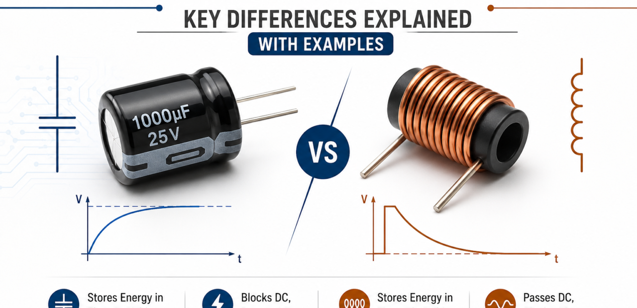
Capacitor vs Inductor: Key Differences Explained with Examples

Capacitors and inductors are two fundamental passive components that power modern electronics, yet they store energy in completely opposite ways. While a capacitor holds electrical energy in an electrostatic field, an inductor stores energy in a magnetic field. Understanding how these components behave is crucial for designing everything from simple power supplies to advanced high-frequency communication circuits.
Choosing between a capacitor and an inductor depends entirely on how your circuit needs to manage voltage and current changes. Capacitors resist sudden changes in voltage, making them ideal for smoothing out signals and filtering noise. Conversely, inductors resist changes in current, acting as energy buffers in power converters and tuning circuits. Together, they form the bedrock of passive circuit design.
Fundamental Working Principles: Electrostatic vs. Magnetic Fields
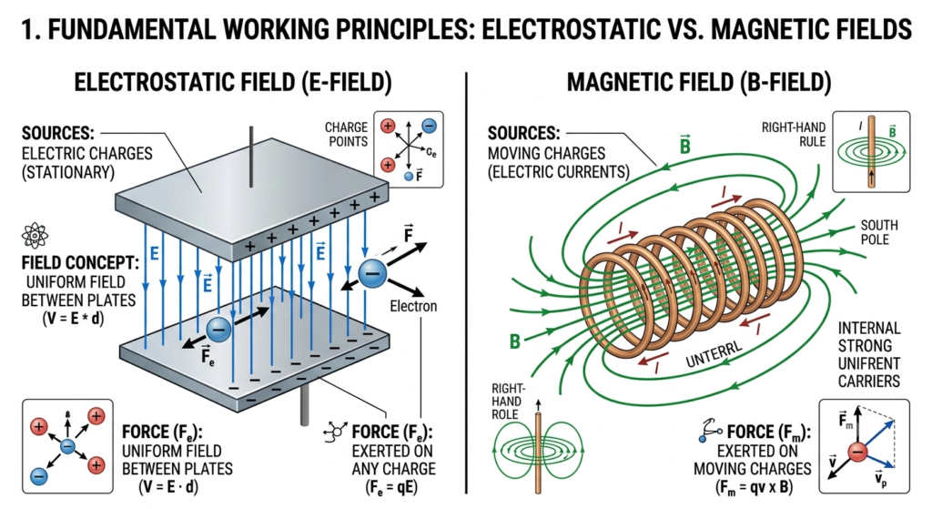
The structural core of a capacitor consists of two conducting plates separated by an insulating dielectric material. When a voltage is applied across the terminal leads, positive and negative charges accumulate on opposing plates, generating an electrostatic field. This field stores electrical energy without allowing direct current to flow through the dielectric, creating a stable potential difference.
An inductor operates on electromagnetism, featuring a conductive wire tightly wound around a magnetic or air core. As electrical current flows through the coil, it establishes a concentrated magnetic field within and around the core loops. If the current changes, the expanding or collapsing magnetic field induces a counter-electromotive force (counter-EMF) that actively opposes the shift in current flow.
Behavior in DC and AC Circuits: Steady-State and Transient Response
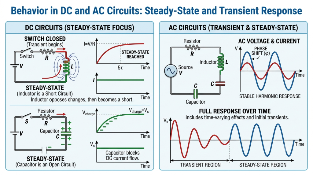
When connected to a direct current (DC) source, a capacitor undergoes a brief charging transient until its terminal voltage equals the supply. Once fully charged, no additional current can flow across the dielectric gap, causing the capacitor to act as an open circuit to steady DC. However, during AC operation, the constant alternation of polarity allows continuous charging and discharging cycles.
An inductor presents low resistance to steady DC signals, acting almost like a simple short-circuit wire once the initial magnetic field is established. During the initial DC turn-on transient, the inductor temporarily blocks current as the magnetic field expands. In AC circuits, the continuously changing current keeps the counter-EMF active, causing the inductor to continuously impede alternating current.
Read More: Application of PN Junction Diode: Types, Uses & Real-World Examples
Core Electrical Behavior: Voltage, Current, and Energy Storage
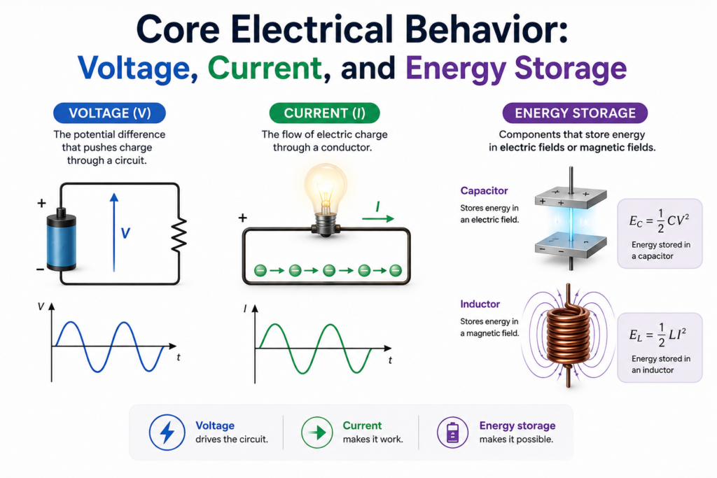
The fundamental distinction lies in how each component reacts to changes over time. A capacitor’s current is proportional to the rate of change of voltage across it, meaning it opposes rapid voltage swings but allows current to flow freely once charged. An inductor’s voltage is proportional to the rate of change of current through it, meaning it opposes rapid current swings while allowing steady current to flow with minimal resistance once stabilized.
This complementary behavior is why capacitors are often described as blocking DC and passing AC, while inductors do the reverse — blocking AC and passing DC. In practical filter design, this single principle determines whether you’re building a low-pass filter, a high-pass filter, or a resonant circuit that combines both components to target a specific frequency range.
Energy storage also differs in nature. A capacitor holds energy proportional to the square of the voltage across it, while an inductor holds energy proportional to the square of the current flowing through it. This distinction becomes critical when designing snubber circuits, surge protection systems, or energy recovery networks where controlling how and where energy gets released can prevent component damage.
Frequency Response and Impedance Characteristics
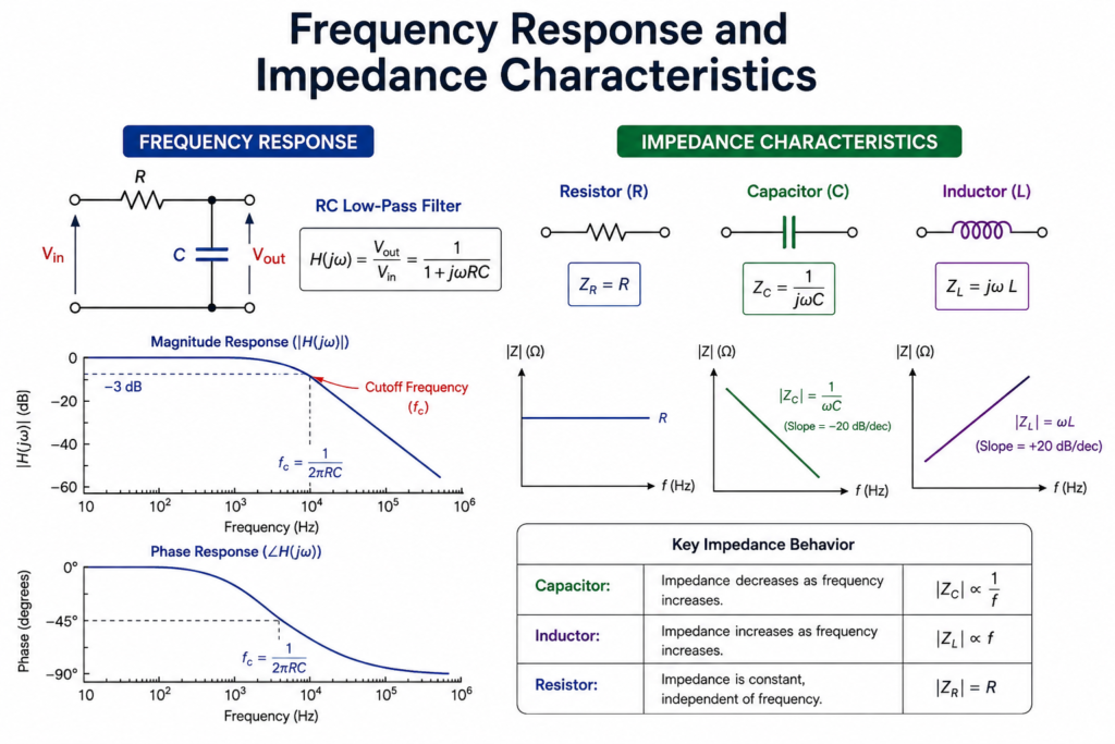
Capacitors and inductors respond to frequency in exactly opposite ways, which is the reason they’re so often paired together in filter and tuning circuits. A capacitor’s impedance decreases as frequency increases, meaning it becomes an easier path for high-frequency signals while blocking low-frequency or DC components. An inductor’s impedance increases as frequency rises, making it harder for high-frequency signals to pass while allowing low-frequency and DC signals through with ease.
This inverse relationship is the backbone of resonant LC circuits, which are widely used in oscillators, radio tuning stages, and impedance matching networks. At a specific frequency called the resonant frequency, the capacitive and inductive reactances cancel out, creating either a very low or very high impedance path depending on whether the components are arranged in series or parallel. Engineers exploit this behavior to isolate or amplify a desired frequency band with impressive precision, which is why LC networks remain foundational even as circuit design shifts toward highly integrated systems.
Real-World Applications: Where Each Component Shines
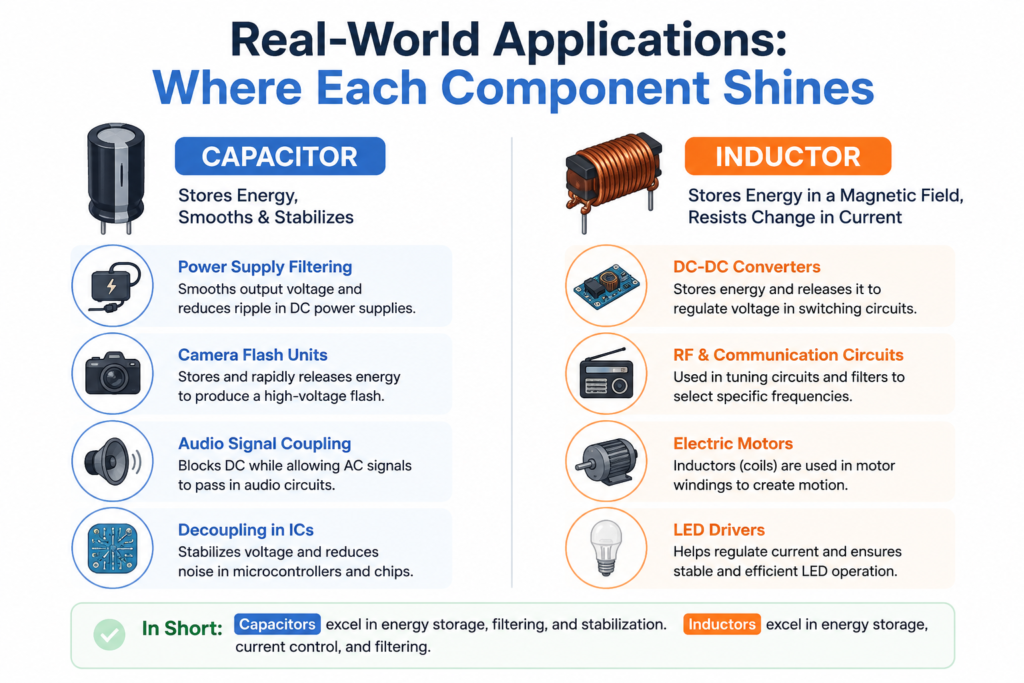
In power supply design, capacitors handle ripple filtering and voltage smoothing, while inductors manage energy transfer and current smoothing in switching regulators — together they form the backbone of nearly every modern DC-DC converter. In audio systems, capacitors couple signals between amplifier stages without passing DC bias, while inductors appear in crossover networks to direct specific frequency ranges to the correct speaker driver.
In radio frequency and wireless communication systems, both components combine in tank circuits to select and amplify specific frequencies, enabling everything from FM radio tuning to impedance matching in antenna networks. In modern chip-level design, capacitors dominate as decoupling and bypass elements due to their compact size, while inductors are used more selectively because they tend to occupy larger physical area — a genuine constraint in dense layouts where every square micron matters.
Quick Comparison at a Glance
| Aspect | Capacitor | Inductor |
|---|---|---|
| Energy stored in | Electric field | Magnetic field |
| Opposes | Change in voltage | Change in current |
| Impedance vs frequency | Decreases with frequency | Increases with frequency |
| Blocks | DC | AC |
| Common use | Filtering, coupling, decoupling | Energy storage, chokes, converters |
Final Thoughts
Capacitors and inductors aren’t competing components — they’re complementary tools that solve different problems depending on what a circuit actually needs. A capacitor smooths voltage and blocks DC; an inductor smooths current and blocks AC. Together, they form the foundation of filters, power converters, and resonant circuits that make modern electronics possible. Knowing exactly when and why to reach for each one is what separates a circuit that merely works from one that performs reliably under real-world conditions.
1. What is the main difference between a capacitor and an inductor?
A capacitor stores energy in an electric field, while an inductor stores energy in a magnetic field. This is the key difference between them.
2. Which is better, a capacitor or an inductor?
Neither is better. Capacitors are ideal for filtering and energy storage, while inductors are best for current control and power conversion.
3. Where are capacitors and inductors used?
Capacitors are used in filters, timing, and power supplies. Inductors are common in transformers, DC-DC converters, and RF circuits.
4. Why does a capacitor block DC but pass AC?
A capacitor charges with DC and stops current flow, but continuously charges and discharges with AC, allowing alternating current to pass.
5. Why does an inductor oppose changes in current?
An inductor creates a magnetic field that generates back EMF, resisting sudden changes in current according to Faraday’s Law.
6. What is the difference between Farads and Henrys?
Farads (F) measure capacitance—the amount of electric charge a capacitor can store per unit of potential difference (Coulombs per Volt). Henrys (H) measure inductance—the amount of electromotive force induced per rate of current change (Volts per Ampere per second).
7. Why are inductors generally larger and more expensive than capacitors in circuit designs?
Inductors require precision wire coils wrapped around physical magnetic cores (like ferrite), making them physically bulkier and harder to miniaturize on integrated circuits. Capacitors can be constructed using thin planar layers, allowing high capacitance in tiny surface-mount device (SMD) footprints.