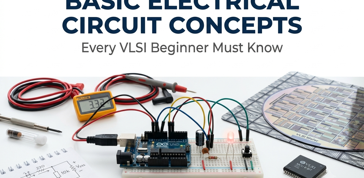
Basic Electrical Circuit Concepts Every VLSI Beginner Must Know

Imagine holding a chip smaller than your fingernail that quietly performs billions of calculations every second. Behind that tiny piece of silicon lies a web of electrical principles so fundamental that skipping them is like trying to build a skyscraper without understanding gravity. If you want VLSI design to actually make sense instead of feeling like memorized jargon, you need to start where every chip designer secretly started too — with basic circuits.
Most people jump straight into layout tools, HDL syntax, or fabrication nodes, assuming the electrical fundamentals will “click” later. They rarely do. Voltage, current, resistance, and the way transistors behave inside a circuit are the actual language chips are written in. Once these ideas feel natural, everything from timing diagrams to power reports starts making a lot more sense.
Voltage, Current, and Resistance: The Real Building Blocks
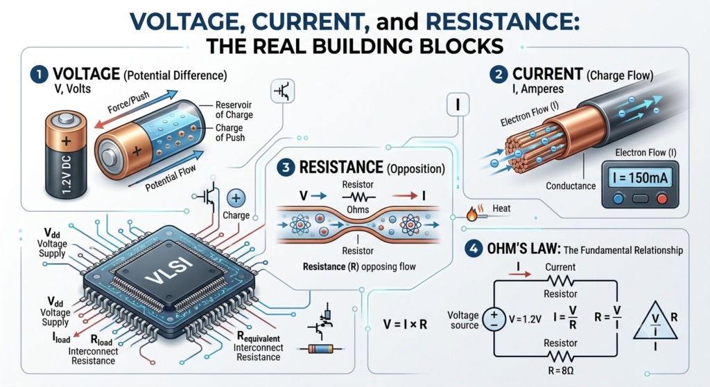
Every circuit, no matter how advanced, is governed by three quantities working together. Voltage is the push — the electrical pressure that drives charge from one point to another. Current is the actual flow of that charge, measured in amperes, and resistance is whatever pushes back against that flow.
In a chip, these aren’t abstract textbook terms. Every wire, every transistor channel, and every interconnect on a die has some resistance, however small. Voltage levels determine how a chip distinguishes a logical high from a logical low, and current flow determines how much heat a design will eventually generate. Designers spend enormous effort keeping voltage stable across a chip because even tiny fluctuations can flip a bit or corrupt a signal. Understanding this trio isn’t optional groundwork — it’s the lens through which every later concept, from power grids to signal integrity, becomes readable.
Ohm’s Law and Power Dissipation in Real Chips
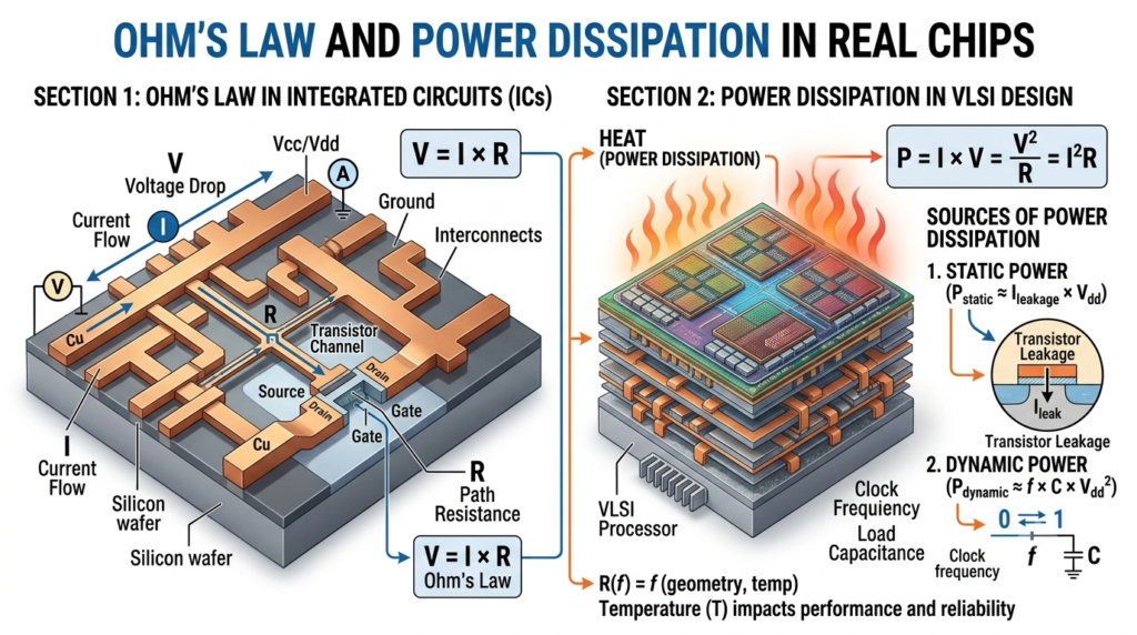
Ohm’s Law feels almost too simple when you first learn it: voltage equals current multiplied by resistance. But inside a modern chip packed with billions of transistors, this simple relationship becomes the reason heat management is one of the hardest problems in the industry.
Power dissipation in a circuit is tied directly to how much current flows and at what voltage. As chips shrink to smaller process nodes, engineers lower voltage to reduce power, but current density per unit area often goes up because more transistors are squeezed into the same space. This tension is exactly why low-power design has become such a major focus in modern semiconductor work. Techniques like dynamic voltage scaling, clock gating, and power gating all trace back to this one basic law. If you understand how voltage and current interact to produce heat, you’ll understand why so much of chip architecture today revolves around squeezing out every unnecessary milliwatt.
Read more :- Analog vs Digital Circuits: Which Is More Important for Electronics Engineers
Digital Logic: How Circuits Actually Represent 0s and 1s
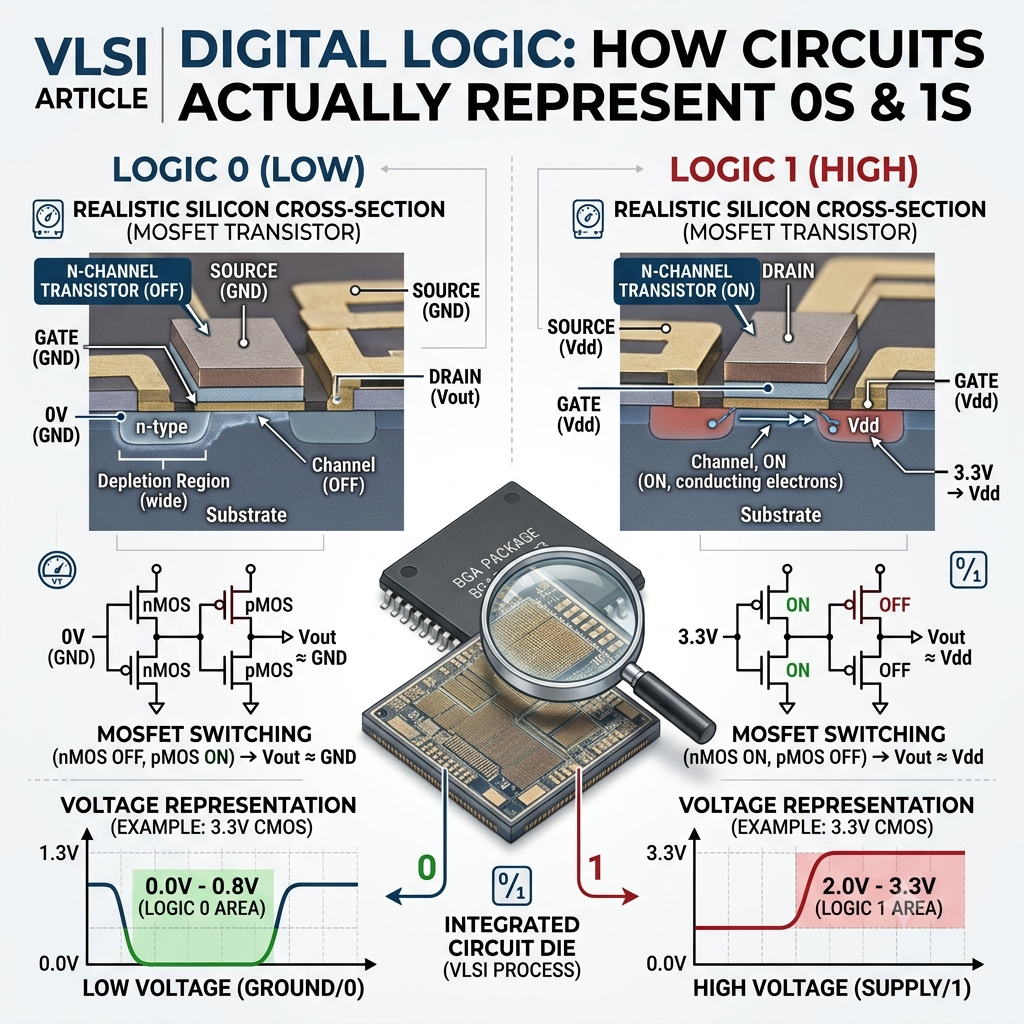
A digital chip doesn’t “know” binary in some abstract sense — it represents it physically, using voltage thresholds. A voltage above a certain level is read as a logical high, and a voltage below another threshold is read as a logical low. Everything in between is treated as undefined or noisy, which is exactly why signal integrity matters so much.
This physical representation is what allows logic gates — AND, OR, NOT, NAND — to be built from nothing but transistors switching on and off. Combine enough of these gates and you get adders, multiplexers, memory cells, and eventually entire processors. What looks like pure logic on a whiteboard is, underneath, a carefully engineered set of voltage levels and switching thresholds. Once this connection clicks, digital design stops feeling like abstract math and starts feeling like physical engineering with predictable, physical rules.
The Transistor as a Switch: CMOS Basics
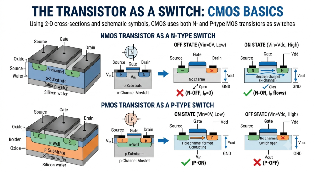
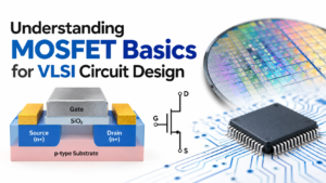
If there’s one component that defines modern chip design, it’s the CMOS transistor. At its core, a transistor is nothing more than a controllable switch — apply the right voltage to its gate, and it either allows current to flow or blocks it.
CMOS technology pairs two types of transistors, PMOS and NMOS, so that at any given moment only one type is conducting. This clever pairing is what keeps power consumption low compared to older transistor technologies, since current barely flows when a gate isn’t actively switching. Almost every logic gate inside a chip is built from these paired transistors arranged in different combinations. Understanding how a single transistor turns on and off is the foundation for understanding how millions of them, working in sync, produce complex digital behavior. It also explains why so much recent innovation — from FinFET structures to newer gate-all-around designs — is really just refining this same basic switching idea to work better at smaller scales.
Capacitance and RC Delay: Why Speed Has Limits
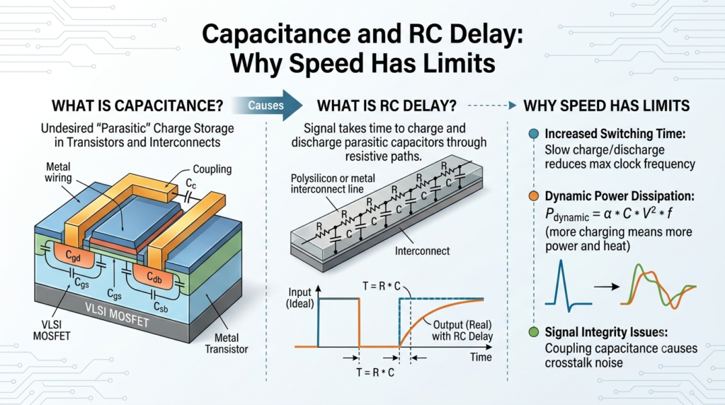
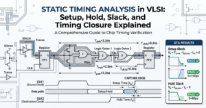
Every wire and every transistor gate in a chip carries a small amount of capacitance, meaning it can store a tiny bit of charge. Combined with the resistance already present in that path, this creates what’s known as RC delay — the time it takes for a signal to charge up or discharge enough to register as a clean logical transition.
This isn’t a minor detail; it’s one of the biggest limiting factors in how fast a chip can run. As designs pack transistors closer together, wires get thinner and interconnect resistance rises, while parasitic capacitance between neighboring lines increases too. That combination directly limits clock speed and is a major reason why architects care so much about interconnect design, not just transistor count. Concepts like buffering, wire sizing, and repeater insertion all exist specifically to fight RC delay. Once you grasp this idea, timing closure reports stop feeling mysterious and start feeling like a direct consequence of basic circuit physics.
Conclusion
Circuit fundamentals might seem like a small starting point compared to the scale of a finished chip, but they’re the thread that connects every layer of VLSI design. Voltage and current explain power. Transistor switching explains logic. Capacitance and resistance explain speed limits. None of it is disconnected trivia — it’s one continuous story, and once you see the pattern, the rest of chip design becomes far easier to follow.
What are the basic electrical circuit concepts for VLSI beginners?
VLSI beginners should learn voltage, current, resistance, Ohm’s law, Kirchhoff’s laws, power, capacitors, inductors, and basic AC/DC circuit concepts.
Why are electrical circuits important in VLSI?
Electrical circuit concepts help VLSI engineers understand transistor behavior, CMOS circuits, signal propagation, power consumption, and chip performance.
What is Ohm’s Law in electrical circuits?
Ohm’s Law explains the relationship between voltage, current, and resistance: V = IR. It is a fundamental concept for understanding electronic and VLSI circuits.
What is voltage and current in a circuit?
Voltage is the electrical potential difference that drives current, while current is the flow of electric charge through a circuit.
What are Kirchhoff’s Laws?
Kirchhoff’s Current Law and Voltage Law help analyze electrical circuits by applying charge conservation at nodes and energy conservation around closed loops.