


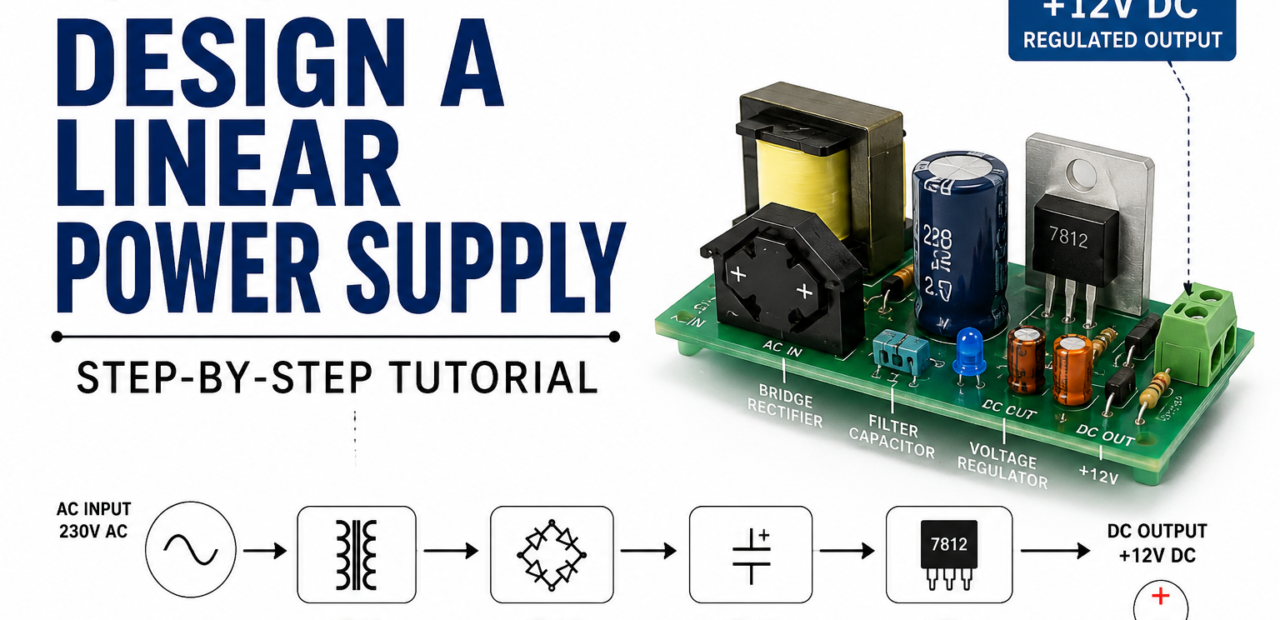
How to Design a Linear Power Supply: Step-by-Step Tutorial

Designing a custom linear power supply remains a fundamental skill for electrical engineers, hobbyists, and hardware developers who need clean, ripple-free DC power. While modern switch-mode power supplies offer high efficiency and compact sizes, they often introduce high-frequency switching noise that can disrupt sensitive analog circuits, audio equipment, and precision measurement tools. Linear power supplies solve this issue by delivering exceptionally quiet voltage outputs with minimal electromagnetic interference.
Building an effective linear power supply requires a clear understanding of four core stages: AC step-down transformation, full-wave rectification, capacitive filtering, and linear voltage regulation. Each stage plays a direct role in determining the output voltage stability, thermal dissipation, and overall reliability under varying loads. This step-by-step guide breaks down the design process from basic circuit principles to thermal management, helping you construct a clean power source tailored to your project.
Mains AC Transformation and Safety Sizing
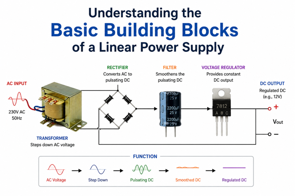
The first stage of a linear power supply lowers high-voltage mains AC (typically 120V or 230V) to a safer, manageable AC level using a step-down transformer. Selecting the correct primary-to-secondary turns ratio ensures the secondary voltage provides sufficient headroom for down-stream components. Engineers must calculate the secondary RMS voltage, keeping in mind that peak AC voltage will equal the RMS value multiplied by 1.414.
Beyond turn ratios, sizing a transformer involves calculating total power requirements in Volt-Amperes (VA). You must account for the continuous load current, diode forward drops, and filter capacitor charging spikes, which draw non-linear current pulses. Adding a safety margin of 20% to 30% above expected maximum power prevents transformer overheating, core saturation, and unwanted output voltage droop under heavy loads.
Bridge Rectification and Diode Selection
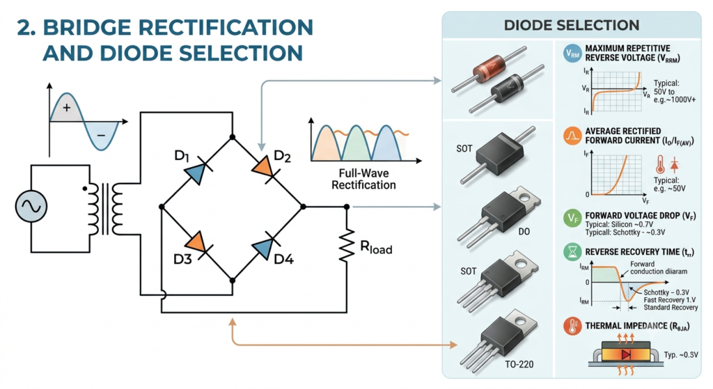
Once the AC voltage is stepped down, it must be converted into unidirectional DC using a bridge rectifier. A full-wave bridge configuration, using four diodes, utilizes both positive and negative halves of the AC sine wave. As current flows, two diodes conduct simultaneously, resulting in a continuous stream of positive voltage pulses at twice the frequency of the incoming AC mains signal.
Selecting the right diodes requires evaluating Peak Inverse Voltage (PIV) and continuous forward current ratings. The PIV rating must exceed the maximum peak AC voltage to prevent junction breakdown during reverse bias. Additionally, each conducting diode causes a forward voltage drop (typically 0.7V for standard silicon or 0.3V for Schottky), which reduces the available peak DC voltage and generates heat under load.
Rectification and Filtering: Converting AC to Smooth DC
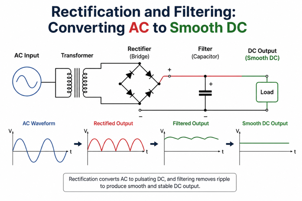
Once you have your AC voltage at the right level, it needs to be converted into DC. A full-wave bridge rectifier, built from four diodes, is the most common choice because it uses both halves of the AC cycle and produces a more continuous output than a half-wave design. When picking diodes, pay attention to peak inverse voltage rating and forward current capacity, and always leave margin above your expected worst-case values.
Rectification alone gives you a pulsing waveform, not clean DC, so a filter capacitor is placed right after the rectifier to smooth things out. The size of this capacitor directly affects ripple voltage — larger capacitance means less ripple, but it also means higher peak inrush current when the supply first powers on. A practical approach is to calculate the minimum capacitance needed for your acceptable ripple level at full load, then round up slightly for margin. Don’t forget to check the capacitor’s voltage rating against the peak rectified voltage, not just the average DC value, since exceeding that rating is one of the most common beginner mistakes.
Read More: Analog vs Digital Circuits: Which Is More Important for Electronics Engineers
Voltage Regulation Techniques for Stable Output
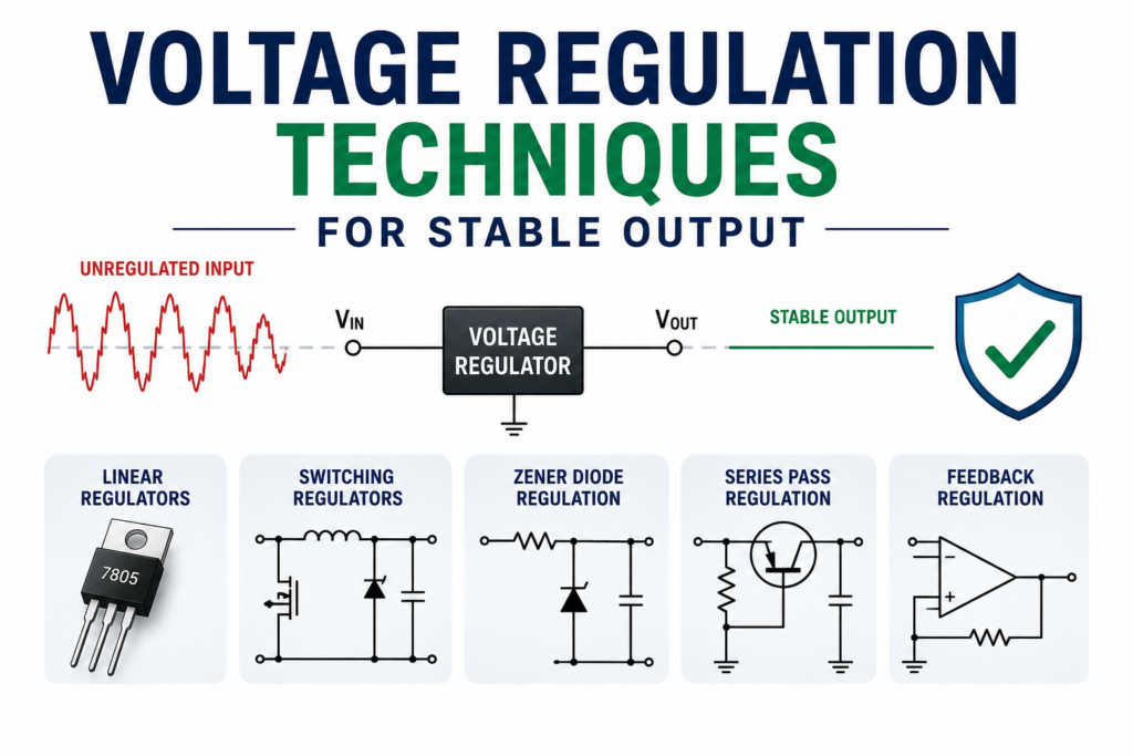
With filtered but still slightly rippled DC in hand, the next job is regulation. Linear regulators, such as the classic three-terminal fixed or adjustable types, work by dropping excess voltage across an internal pass transistor to hold the output constant. They’re simple to wire, require few external parts, and produce very low output noise, which is exactly why they remain popular in audio and instrumentation circuits where switching noise would be a problem.
The trade-off is efficiency. Because a linear regulator dissipates the difference between input and output voltage as heat, the larger that voltage gap, the more power gets wasted rather than delivered to the load. This is why transformer selection earlier in the process matters so much — keeping the regulator’s input voltage just high enough above the target output minimizes wasted power and heat. For higher current designs, it’s worth comparing a basic three-terminal regulator against a low-dropout variant, since LDOs can operate with a much smaller voltage difference and improve overall efficiency.
Thermal Management and Practical Design Tips
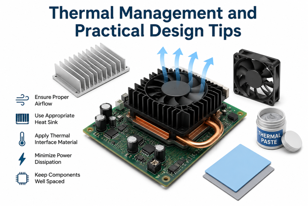
Heat is the constant companion of any linear supply, and managing it properly is what separates a reliable design from one that fails after a few months of use. Start by calculating the actual power the regulator will dissipate under worst-case conditions — maximum input voltage and maximum load current — and use that figure to choose an appropriate heatsink. Manufacturer datasheets typically include thermal resistance values that let you estimate junction temperature directly, so there’s no need to guess.
Beyond heatsinking, a few practical habits go a long way. Add reverse-polarity protection and a fuse on the primary side for basic safety. Place decoupling capacitors close to the regulator’s input and output pins to prevent oscillation, especially with older regulator designs that are sensitive to output capacitor characteristics. Route high-current traces with adequate width, and keep sensitive feedback or reference nodes away from noisy paths. None of these steps are complicated on their own, but together they’re what turns a working prototype into a supply you can trust in the field for years.
Bringing It All Together
Designing a linear power supply comes down to understanding how four stages hand off responsibility to one another: the transformer sets the voltage, the rectifier flips AC into pulsing DC, the filter smooths it out, and the regulator locks it in place. None of these stages is difficult in isolation, and once you’ve built one supply from scratch, the process becomes second nature for the next.
Linear supplies aren’t always the most efficient option on paper, but for applications where clean, quiet, and predictable power matters more than squeezing out every last percentage point of efficiency, they remain a genuinely solid choice. Whether you’re building a bench supply, powering a sensitive analog circuit, or just want to understand the fundamentals before moving on to switching designs, working through these five stages by hand is one of the best ways to build real, lasting intuition about how power electronics actually work.
1. What is a linear power supply?
A linear power supply converts AC to stable DC using a transformer, rectifier, filter capacitor, and voltage regulator for clean, low-noise output.
2. How do you design a linear power supply?
Choose the output voltage and current, select a transformer, bridge rectifier, filter capacitor, voltage regulator, and add proper heat sinking.
3. What components are required for a linear power supply?
A transformer, bridge rectifier, filter capacitor, voltage regulator IC, heat sink, fuse, and output capacitor are the main components.A transformer, bridge rectifier, filter capacitor, voltage regulator IC, heat sink, fuse, and output capacitor are the main components.
4. Why use a linear power supply instead of SMPS?
Linear power supplies provide cleaner, low-noise DC output, making them ideal for audio circuits, lab equipment, and sensitive electronics.
5. How does a bridge rectifier work?
A bridge rectifier converts AC voltage into pulsating DC using four diodes, allowing current to flow in the same direction through the load.
6. Can I use Schottky diodes instead of standard silicon diodes in the rectifier?
Yes, Schottky diodes offer lower forward voltage drops (~0.3V compared to ~0.7V for silicon diodes), which reduces power loss and heat generation at the bridge rectifier. They also offer faster recovery times, making them an excellent choice for low-voltage, high-efficiency designs.
7. How can I protect my linear power supply from short circuits and overload?
You can protect your power supply by placing a fuse on the primary transformer input, selecting a linear regulator with built-in current limiting and thermal shutdown (like the LM317 or LM7805), and adding protection diodes across the regulator to prevent reverse-current damage during shutdown.