



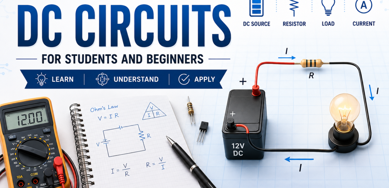
Beginner Guide to DC Circuits for Students and Beginners

Understanding Direct Current (DC) circuits is the foundational first step for anyone entering electronics or electrical engineering. Unlike alternating current, DC provides a steady, unidirectional flow of electric charge that powers our most essential everyday devices, from smartphones to electric vehicles. Mastering these basic concepts builds the practical logic needed to troubleshoot, design, and innovate in modern technology.
Navigating circuit theory can seem intimidating, but breaking down the core principles makes it accessible to every beginner. By learning how voltage, current, and resistance interact, students gain a clear mental model of how electricity behaves in a closed loop. This guide breaks down essential components, key mathematical laws, and common circuit configurations to help you build a solid foundation in electronics.
Understanding the Core Elements: Voltage, Current, and Resistance
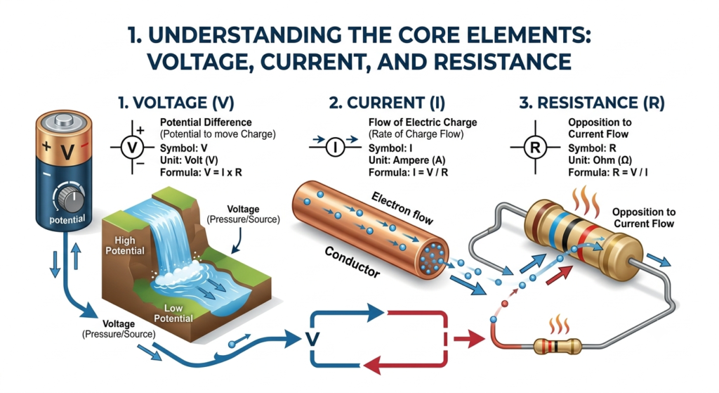
Electric circuits rely on three fundamental properties to function: voltage, current, and resistance. Voltage acts as the electrical pressure pushing charge through a conductor, measured in volts. Current represents the actual flow rate of electrons passing a given point per second, measured in amperes. Understanding these core terms is essential for visualizing how electrical energy moves through any circuit setup.
Resistance serves as the natural opposition to electric current, measured in ohms. Materials like copper offer low resistance, while insulators like rubber restrict charge flow entirely. Controlling resistance allows engineers to limit current and protect sensitive components from damage. Together, these three properties form the basic framework for predicting and controlling electrical behavior in direct current systems.
The Core Components You’ll Keep Running Into

Before diving into calculations, it helps to get comfortable with the physical building blocks. Resistors limit or control the flow of current and are measured in ohms. Capacitors store energy temporarily and release it when needed, which is useful for smoothing out power fluctuations. Inductors resist sudden changes in current, storing energy in a magnetic field rather than an electric one.
Then there are power sources, which can be batteries, power supplies, or regulated voltage sources depending on the application. Switches control whether current flows at all, and diodes allow current to move in only one direction, acting like a one-way valve. Once you can identify these components on a circuit diagram and understand their basic role, reading and building circuits becomes far less intimidating.
A good habit early on is to physically trace circuits, either on paper or with real components, rather than just memorizing definitions. Seeing how current actually behaves when it hits a resistor versus a capacitor builds an intuition that no textbook explanation alone can fully replace.
Read More: MOSFET vs Transistor: Key Differences, Working, Advantages & Applications
Demystifying Ohm’s Law: The Golden Formula of Electronics
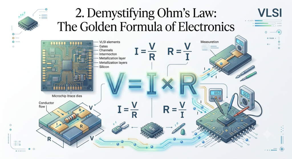
Ohm’s Law is the central mathematical relationship governing DC circuits, defined by the formula $V = I \cdot R$. This fundamental equation states that voltage equals current multiplied by resistance. By rearranging this simple formula, students can easily calculate an unknown value whenever the other two variables are known. It forms the mathematical backbone for designing and analyzing simple to complex circuits.
Applying Ohm’s Law in practice helps prevent component failure and optimizes energy delivery. For instance, if you apply a known voltage across a resistor, you can calculate the precise current flow to ensure your components operate safely. Mastering this single relationship enables beginners to analyze real-world circuits with confidence before ever picking up a soldering iron or multimeter.
Series and Parallel Circuits: Why the Difference Matters
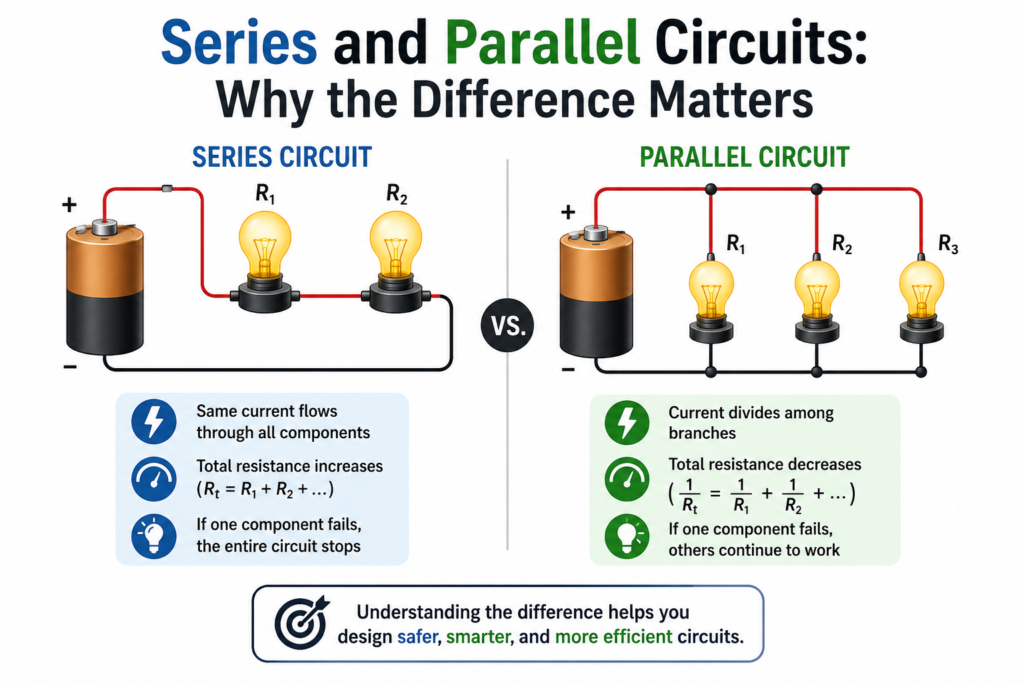
Circuits are typically arranged in one of two configurations, and knowing the difference changes how you calculate everything. In a series circuit, components are connected end to end, forming a single path for current. This means the same current flows through every component, but the voltage divides across each one based on its resistance. If one component in a series circuit fails, the entire circuit breaks, since there’s only one path for current to travel.
In a parallel circuit, components are connected across the same two points, creating multiple paths for current to flow. Here, the voltage across each branch stays the same, but the current divides based on the resistance of each path. This is why household wiring uses parallel configurations — if one appliance fails or is switched off, the rest continue operating normally.
Many real circuits combine both configurations, creating series-parallel networks that require breaking the circuit down into smaller, manageable sections before applying Ohm’s and Kirchhoff’s Laws. Practicing with these mixed circuits is one of the fastest ways to build genuine confidence, because it forces you to think systematically rather than relying on formulas alone.
Where DC Circuit Concepts Show Up in Modern Chip Design
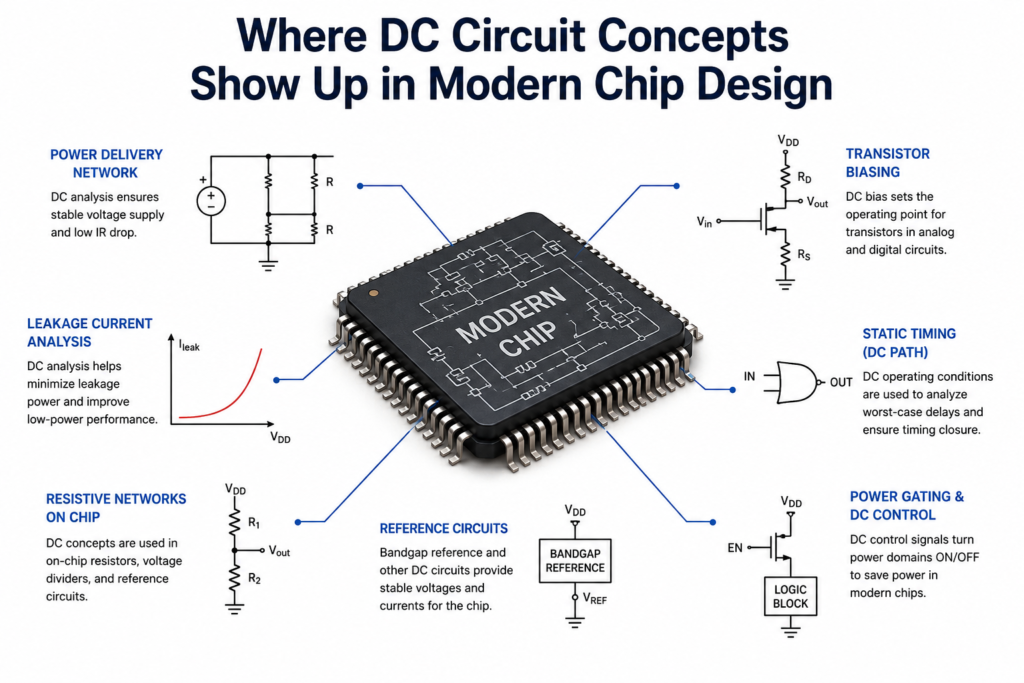
It’s easy to assume that basic DC circuit theory becomes irrelevant once you move into advanced electronic systems, but the opposite is true. Inside every integrated circuit, at the transistor level, the same fundamental rules govern how current moves and how voltage behaves across each tiny component. Power distribution networks within a chip, for instance, are essentially vast, carefully engineered DC circuits designed to deliver stable voltage to millions of transistors simultaneously.
Understanding basic resistance, current division, and voltage drop directly translates into understanding why certain regions of a chip might experience voltage sag under heavy load, or why power planning matters so much during the design phase. Concepts like IR drop analysis, a major consideration in modern chip layouts, are really just an application of Ohm’s Law across a much larger and more intricate network.
Even as circuits shrink to nanometer scales and involve billions of transistors, the underlying behavior traces back to the same principles you’d use to analyze a simple battery-and-resistor setup. This connection is part of what makes a strong grasp of DC fundamentals so valuable — it doesn’t just help you pass an early milestone, it stays relevant no matter how advanced your work eventually becomes.
Conclusion
DC circuits might seem elementary compared to the complexity of modern electronic systems, but that simplicity is precisely their strength. They offer a clear, predictable framework for understanding how electrical energy moves, transforms, and does useful work. Every advanced concept you’ll encounter later, from signal integrity to power management in dense chips, rests on this same foundation.
The best way forward is practice: build small circuits, calculate values by hand before checking with a simulator, and get comfortable seeing how theory translates into real, observable behavior. Master this groundwork well, and every advanced topic that follows will feel far less like a mystery and far more like a natural extension of what you already know.
1. What is a DC circuit?
A DC circuit is an electrical circuit where current flows in one direction from a DC power source like a battery, powering devices consistently.
2. What are the basic components of a DC circuit?
A DC circuit includes a power source, wires, a load such as a resistor or bulb, and often a switch to control current flow.
3. Why should beginners learn DC circuits first?
DC circuits are simple to understand and form the foundation for learning electronics, electrical engineering, and circuit design.
4. What is the difference between DC and AC circuits?
DC current flows in one direction, while AC current changes direction periodically. Beginners usually start with DC because it is easier.
5. Where are DC circuits used?
DC circuits are used in batteries, smartphones, laptops, electric vehicles, solar systems, LEDs, and many electronic devices.
6. Can I measure current with a multimeter without breaking the circuit loop?
No, to measure current with a standard multimeter, the meter must be placed in series within the circuit so that the electric current flows directly through the instrument.
7. Why is a breadboard useful for beginners learning DC circuits?
A breadboard allows students to build and test electrical circuits temporarily without soldering. Components can easily be plugged in and rearranged, making it ideal for learning, experimentation, and rapid prototyping.